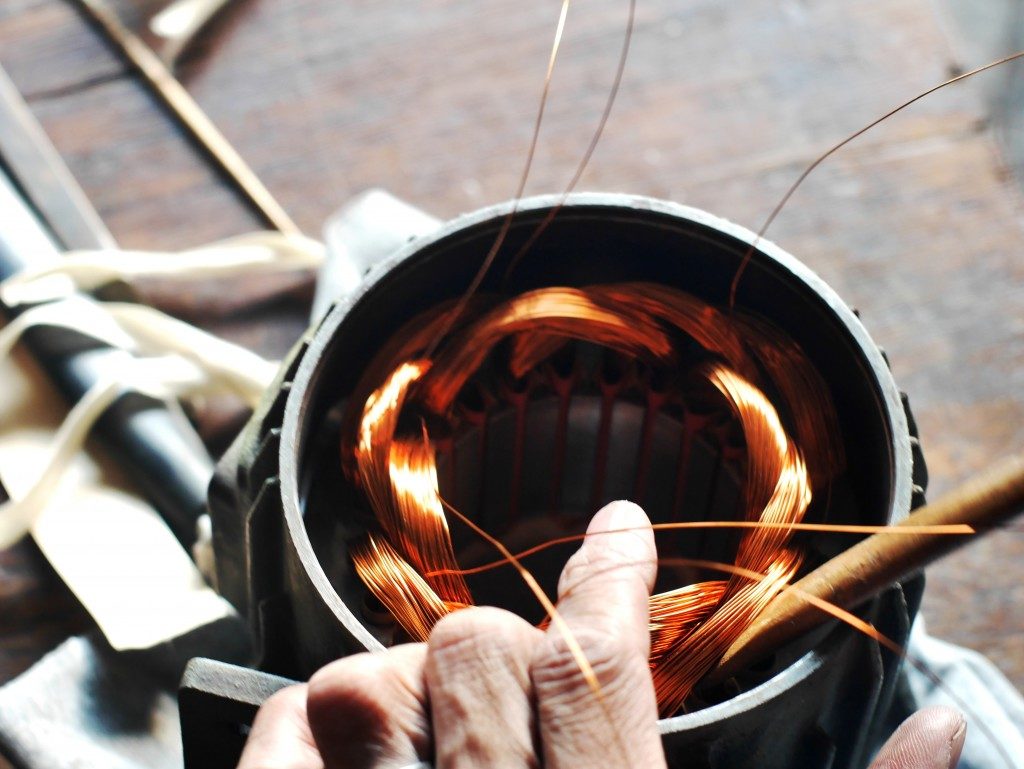
The transformer is typically the most crucial element in most of machines. The vital component of the transformer is its windings. These are conductors that will be wrapped in different configurations around the transformer. They will generate a magnetic field that will be carried to the core of other windings and generate varying voltage levels.
There are two transformer winding types: shell and core type transformers. Shell type windings have their primary and secondary windings on their inner limbs. They have a high mechanical and dielectric strength, compact size, and flexible design.
An industrial machine shop in Trinidad will mostly have core type windings for their transformers. These windings have their secondary and primary windings on the exterior aspect of their limbs. They prevent condensed flux leakage, support high frequencies, and have high mechanical strength. Here are the core-type windings that can be used for your transformer.
Cylindrical Windings
These use voltages of 6.6 kV for 600 to 750 kVA and feature current ratings of 10 to 600A. Cylindrical windings will generally be used in multi-layered configurations in combination with rectangular double-layered conductors. This makes the securing of lead-out ends in your transformer easy. Circular conductors are wound around vertical strips in multi-layered windings to boost their cooling conditions.
Helical Windings

These are used in high capacity transformers for low voltage when the current is high while the winding turns are minimal. For helical windings, the standard transformer output varies from 0.23 to 15 kV. The cross-sectional strip areas of helical windings are at least 75 to 100 mm square to guarantee an adequate mechanical strength for the transformer. The maximum strip number used in the conductor in a parallel arrangement is 16. Single, double, multi-layered, and disc-helical windings are the three types of helical windings.
Crossover Windings
These are used in high voltage windings in small transformers. The conductor, in this instance, will be covered with round wires or paper-covered strips. They decrease the voltage between the adjacent winding layers since they will be divided into several coils separated axially by 0.5 to 1mm. The voltage between these coils is between 800 and 1000v at most. Under normal conditions, crossover windings are significantly stronger compared to cylindrical windings, though they have a lower impulse strength. The initial installation and rewinding of crossover windings are nonetheless labor-intensive. Machines with these windings might be relatively costly.
Continuous Disc and Disc Windings
These are used in high capacity transformers. They are comprised of several flat discs or coils in a parallel or series configuration. The coils in the continuous disc and disc windings are created using rectangular strips that will be spirally wound in a radial direction from the center outwards. Their formation makes the construction of the windings extremely strong yet cheap. The conductor’s area ranges from 4 to 50mm square with current limits of 12 to 600 A.
The ideal choice for your machine’s transformer from the ones above depends on several factors. The primary ones include the surge voltage, temperature rise limits, withstanding capacity of the short circuit, and the current rating or your machine. It is prudent to get your machine from a knowledgeable supplier who will guide you on the best winding for your application. Getting one who can also handle the machine’s repairs is an added advantage.

